PRODUCTIVITY
BOOSTERS
How can we minimise build time and cost per part with metal AM? | APRIL 12, 2022 | by Dr. Dieter Schwarze
BACK TO OVERVIEW
At the end of the 1980s, layer-by-layer production technologies began to grow, summarised under the term "Rapid Prototyping," wherein the word rapid maybe was somewhat misleading, at least from today's perspective. Nevertheless, it had the touch of a revolution, which is true even more now concerning the present capabilities of additive manufacturing (AM) technologies like SLM®.
In 2021 the evolution of Selective Laser Melting (SLM®) had reached a generation-long history. During that time, its technological borders were pushed with irrepressible enthusiasm and ability. Still, the rush for more productivity and reduced cost per part is ongoing…
One way of drastically reducing production time can be achieved by reducing a part's density in certain regions or wherever possible without harming the part's usage.
One example of this has come to age already but is still a valid application even 17 years later. A two-piece steel tool consisting of an upper and a lower tool was built by SLM® using a shell production method. For both tools, the volume inside a solid 100% dense 2.5 mm thick tool-hull was filled with crisscross x-y supports surrounded by the unsolidified steel powder. Utilising this method, the building time was reduced by more than a factor of two. The tools were successfully used on a 55-ton press for stamping 3 mm thick sheet metal parts (see Figure 1) with width ~150 mm, length ~250 mm, and height ~30 mm (see ball pen for scale).
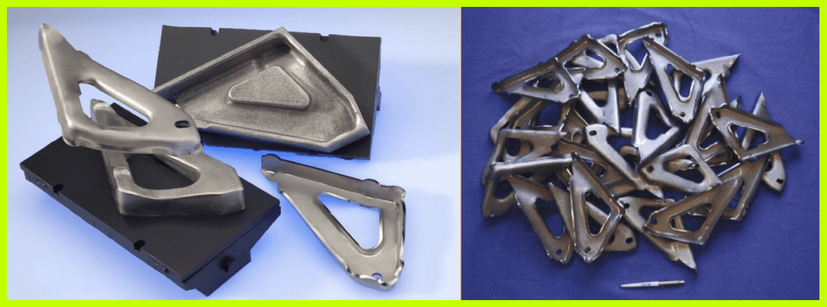 Figure 1: Upper and lower tool with two stampings (left) and a pre-series of sheet metal stampings (right).
The disadvantage of the previously described build time minimisation by way of shell production is the non-solidified region within the shell, leading to totally different mechanical part properties compared to a fully solidified one.
Hold it! While writing this article, a brand-new publication titled "Fatigue performance of shelled additively manufactured parts subjected to hot isostatic pressing" appeared in Additive Manufacturing, Vol. 51, March 2022.
It says:
"It has recently been demonstrated that metal AM components can be manufactured through printing a shell only – therefore with process powder remaining enclosed in the part – whereby the subsequent HIP cycle fully densifies the material. This approach has some advantages, including primarily a reduction in laser processing time during the L‑PBF process, acting to reduce total costs."
So don't hesitate to use shell AM where possible and look at the publication where this was written. Thanks to the authors.
That's not all, of course. The bouquet of possibilities for productivity boosters is quite large.
Over the past two and a half decades in numerous publications, the energy density E showed a very good value in judging if the metal powder bed fusion (PBF) process would likely lead to acceptable parts. The equation:
is even older than SLM® technology itself. And the good thing about it? It's easy to work with. L is the laser power in Watt, v the scan velocity, Δy the hatch distance (or track distance), and Δz the layer thickness. The denominator (v*Δy*Δz) is the build rate.
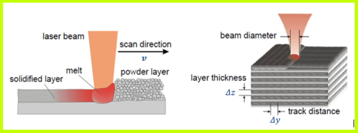 Figure 2: Illustration for the SLM® melting process (pictures courtesy of FhG ILT Aachen)
The equation for E tells us that if one has produced a high-density part with one set of the four variables L, v, Δy, and Δz and then would like to develop another parameter set with double laser power 2 L, that then, for example, the scan velocity could be doubled to 2 v also.
Really? Well, don't take it for granted. For SLM® parameter development, the energy density is an excellent indicator, for good and worse. The simple energy density equation describes ranges in which the SLM® process works very well. Reducing it too much would lead to a lack of fusion and an unstable melting process; increasing it too much would lead to overheating, material evaporation, and keyhole porosity, leading to an unstable melting process.
Enlarging the laser power L isn't a big problem today. An even stronger boost of the SLM® process can be achieved by combining more laser power L with an increased layer thickness Δz. This is a better idea than just enlarging the laser power at constant layer thickness and faster scan speed. Figure 3 shows an example of a part's evolution stages with four-parameter combinations using three different layer thicknesses of 30 µm, 60 µm and 90 µm and two different laser powers of 400 W and 700 W.
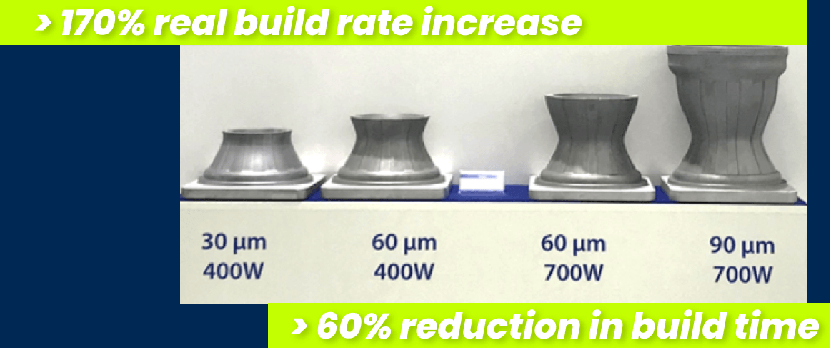 Figure 3: Evolution of a part within a predefined build time at different Δz and laser power
Within the predefined build time, the part was built to the full height using 90 µm layer thickness at 700 W, shown on the right. Using 30 µm layer thickness at 400 W, shown on the left side, approximately only a third of the total height could be built. An incredible real build rate increase of more than 170% is between the two-parameter sets, translating to a build time reduction of 60%. Fantastic values, and real!
We didn't touch the hatch distance until now. Doubling the hatch distance in the denominator of the energy density equation would result in a corresponding doubling of the build rate. The hatch distance in the equation is a simplified expression of one laser beam parameter, in this case, the spot diameter of the focused laser beam at the surface area of the powder bed. Doubling the hatch distance means a doubling of the spot diameter. Referring back to the statements above about the ranges of the energy density concerning a good working window, one needs more laser power and/or, for example, a lower scan speed simultaneously.
In 2011, we conducted our first experiments with a 1 kW multi-mode fibre laser in an SLM®250HL machine equipped with an adapted common optical bench. With a single-mode fibre laser, the achieved spot diameter was approx. 80 µm, and with the multi-mode laser, it was more than 5x larger. However, this doesn't mean that it translates to a 5x productivity increase. The energy density equation provides a simplified interpretation of the SLM® process and the physics behind it. It tells nothing about the optical absorption properties of the metal powder nor heat dissipation and other material properties, but they are implicitly included. We produced fully dense stainless steel test parts with a hull & core strategy using a 400 W single-mode laser for the hull and the additional 1 kW multi-mode laser for the core. Compared to the hull, we achieved a productivity gain of 3x in the core area with a hatch distance of approximately 500 µm.
SLM Solutions is the technology leader in laser metal powder bed fusion. The introduction of the world's first multi-laser metal AM machine in 2012 was a milestone for SLM Solutions and the entire AM community. Today, most of our products are multi-laser machines for SLM® serial production. All productivity boosters mentioned before are possible with our current state-of-the-art SLM® machines.
Figure 4 gives an example of the time reduction and the corresponding productivity booster value in a case study of a cylinder head produced using AlSi10Mg on an SLM®500 Quad compared to a similar SLM®500 Twin machine, i.e., a comparison between a four laser and two laser system shows a 78% increase in productivity.
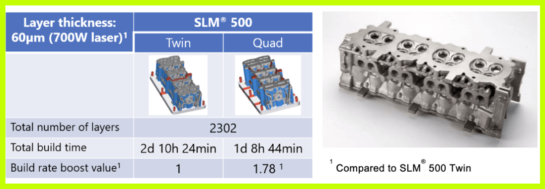 Figure 4: Productivity comparison between two lasers vs four lasers using SLM® at Δz = 60 µm and 700 W laser power showing a 78% booster value
This example shows a productivity increase of nearly a factor of two. But here at SLM Solutions, we did even more. On the 10th of November 2020, we showed the world something totally new. Our team culminated its efforts to enhance productivity by launching an incredible new product: the NXG XII 600. Utilising 12 lasers of 1000 W each and a build volume of 600 x 600 x 600 [mm], the NXG XII 600 is an unrivalled productivity giant that beckons a new era of industrialisation for AM.
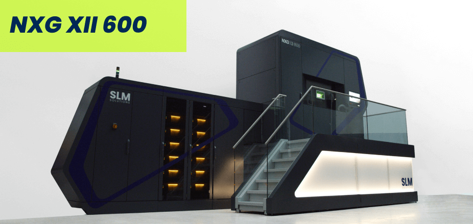 Figure 5: The NXG Xll 600
With 5x the productivity of an already leading SLM®500 Quad and up to 20x as productive as a single laser system, the rules for metal additive manufacturing have been rewritten – yet the equation for energy density remains constant.